
1. Introduction
Resistor types and selection criteria are essential for the stability and functionality of modern electronic circuits. Resistors help control current, divide voltage, and protect sensitive components from damage. Whether you’re working with consumer devices, automotive systems, or IoT innovations, understanding resistor types and selection criteria is critical to ensuring reliable and efficient designs.
In this article, we’ll explore the key aspects of resistor types, their key parameters like power dissipation, tolerance, and temperature coefficient (TCR), and configurations. Additionally, we’ll cover practical resistor selection criteria, helping you make informed decisions when choosing resistors for your own projects.
2. Fundamentals of Resistance
2.1 Core Principles
Resistance is a measure of how much a material opposes the flow of electric current. It is a critical parameter in designing and analyzing circuits. The relationship between resistance (R), voltage (V), and current (I) is defined by the Ohm’s Law formula :
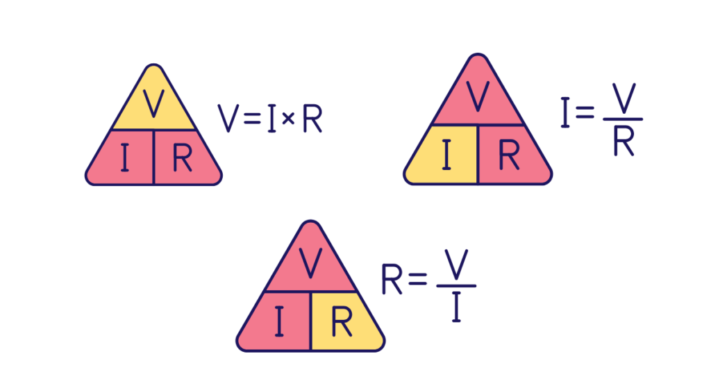
This equation is fundamental in circuit design, helping engineers calculate and control current flow in various applications.
2.2 Resistivity
The resistance of a material depends on the type of material used (its resistivity, an intrinsic property) and its geometry, expressed as:
\(R = \rho \cdot \frac{L}{A}\)
Where:
R: Resistance
ρ: Resistivity of the material (Ω⋅m)
L: Length of the material (m)
A: Cross-sectional area (m²)
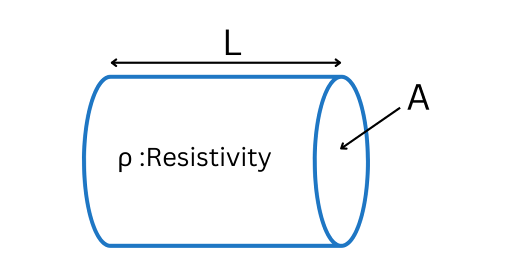
This formula is essential in resistor design, helping engineers determine how material properties and dimensions impact resistance. By selecting appropriate materials and optimizing geometry, designers can meet specific performance and reliability requirements.
2.3 Resistor Power Dissipation
When resistors control current in a circuit, they convert electrical energy into heat through the Joule effect. This fundamental phenomenon occurs as moving electrons collide with the atoms of the resistive material, transferring energy and causing it to heat up. The heat generated can be quantified using the power dissipation formula:
$$ P = I^2 \cdot R $$
Here, P represents power (in watts, W).
This equation demonstrates how power dissipation increases significantly with higher currents, making it crucial to choose resistors that can safely handle the required power.
3. Resistor Configurations: Series, Parallel
Resistors can be connected in different configurations depending on the circuit requirements. Two of the most common configurations are series and parallel.
3.1 Series Configuration
In a series configuration, resistors are connected end-to-end, so the same current flows through all the resistors. The total resistance is the sum of individual resistances:
$$R_{\text{total}} = R_1 + R_2 + R_3 + \dots + R_n$$
Example: If three resistors of 1kΩ are connected in series, the total resistance is:
$$R_{\text{total}} = 1 \, \text{k}\Omega + 1 \, \text{k}\Omega + 1 \, \text{k}\Omega = 3 \, \text{k}\Omega$$
3.2 Parallel Configuration
In a parallel configuration, resistors are connected so that their ends are linked to the same two nodes. The total resistance is determined by the reciprocal sum formula:
$$\frac{1}{R_{\text{total}}} = \frac{1}{R_1} + \frac{1}{R_2} + \frac{1}{R_3} + \dots + \frac{1}{R_n}$$
For two resistors in parallel, the total resistance simplifies to:
$$R_{\text{total}} = \frac{R_1 \cdot R_2}{R_1 + R_2}$$
Example: If two resistors of 1.2kΩ and 2.2kΩ are connected in parallel, the total resistance is:
$$\frac{1}{R_{\text{total}}} = \frac{1}{1200} + \frac{1}{2200}$$ $$R_{\text{total}} = 680 \, \Omega$$
4. Resistor Key Electrical Characteristics
Resistors have several key electrical characteristics that influence their performance and suitability for various applications. Below is a breakdown of these characteristics and their significance, with a focus on how they relate to resistor types and selection criteria:
4.1 Resistance Value
Resistor values are organized into standardized E-series groups, such as E3, E6, E12, E24, E48, E96, and E192, defined by their tolerance levels. These series ensure consistent spacing of values on a logarithmic scale, simplifying the selection of components for various applications.
For a detailed table of all E-series values, refer to the Vishay Standard Series Table.
4.2 Tolerance
Tolerance defines the allowable variation in a resistor’s actual resistance value from its nominal value, expressed as a percentage (e.g., ±1%, ±5%).
Tight Tolerance (e.g., ±0.1% to ±1%): Critical for precision applications like medical devices and instrumentation.
Loose Tolerance (e.g., ±5% or ±10%): Sufficient for general-purpose circuits.
The tolerance determines the acceptable resistance range. For example, a 10kΩ resistor with ±5% tolerance has a range of 9.5kΩ to 10.5kΩ.
4.3 Power Rating
As defined in 2.3 Resistor Power Dissipation, resistors convert electrical energy into heat through the Joule effect. To handle this heat safely, resistors are categorized by their power rating, which defines the maximum power they can dissipate without overheating.
Resistors are available in standard power ratings to suit various applications, as shown in the table below:
| Resistor Type | Typical Ratings | Applications |
| Low Power Resistors | 0.125W, 0.25W, 0.5W, 1W | Signal processing, voltage dividers, filters. |
| High Power Resistors | 2W, 5W, 10W, 25W, higher | Power supplies, precharge circuits, |
4.4 Temperature Coefficient of Resistance (TCR)
The Temperature Coefficient of Resistance (TCR) measures how a resistor’s resistance changes with temperature, expressed in parts per million per degree Celsius (ppm/°C). A lower TCR indicates better stability, making it essential in precision and temperature-sensitive applications.
What is PPM?
PPM (Parts Per Million) is a unit used to express small changes or variations in a value.
For resistors:
- 1 ppm/°C means the resistance changes by 1 millionth (0.0001%) of its nominal value for every degree Celsius of temperature change.
- Example: For a 1kΩ resistor, 1ppm/°C equates to a 0.001Ω change per degree Celsius.
TCR Formula :
The resistance at a given temperature can be calculated as:
$$R(T) = R_0 \cdot \left(1 + TCR \cdot \Delta T\right)$$
Where:
- R0 : Resistance at the reference temperature.
- Δ𝑇: Temperature change ( 𝑇 − 𝑇0)
- 𝑇𝐶𝑅: Temperature Coefficient of Resistance in ppm/°C.
Example Calculation :
Suppose a 1kΩ resistor with a TCR of 100ppm/°C operates at a temperature increase of 50°C (from 25°C to 75°C):
Calculate the fractional change in resistance:
$$TCR \cdot \Delta T = 100 \cdot 10^{-6} \cdot 50 = 0.005$$
Determine the new resistance: $$R(T) = 1.005 \, \text{k}\Omega$$
The resistance increases by 5Ω.
Applications of TCR :
Precision Circuits: Low TCR resistors are used in applications like measurement instruments, ensuring accuracy despite temperature changes. T
Temperature Compensation: Resistors with predictable TCR are used in compensation circuits to counteract temperature effects.
4.5 Thermal Noise (Johnson Noise) in Resistors
Thermal noise, also known as Johnson noise, is an inherent type of noise that exists in all resistors. It is caused by the random thermal motion of electrons within the resistor material. As temperature increases, the random motion of the electrons becomes more intense, producing voltage fluctuations across the resistor, even in the absence of an applied current or external voltage. This noise is always present in resistors at non-zero temperatures and increases with both resistance and temperature.
Thermal Noise Power Formula :
The thermal noise voltage ( Vnoise ) can be calculated using the following formula:
$$V_{\text{noise}} = \sqrt{4 \cdot k \cdot T \cdot R \cdot \Delta f}$$
Where:
- Vnoise : is the RMS noise voltage in volts (V).
- k: is the Boltzmann constant.
- T is the temperature in Kelvin (K).
- R : is the resistance in ohms (Ω).
- Δf : is the bandwidth in hertz (Hz), which refers to the range of frequencies over which the noise is measured.
Example Calculation :
For a 1kΩ resistor at 298K with a 10kHz bandwidth, the thermal noise voltage is:
$$V_{\text{noise}} \approx 0.406 \, \mu\text{V}$$
Impact of Thermal Noise on Circuits :
Thermal noise can influence the performance of circuits, particularly in applications that are sensitive to low-level signals:
Signal Distortion: Thermal noise can distort the signal in systems like audio amplifiers, measurement devices, and communication circuits.
Measurement Accuracy: In precision circuits such as those used in scientific instruments or medical devices, thermal noise can degrade the accuracy of readings.
High-Resistance Circuits: Thermal noise is more noticeable in high-resistance circuits or systems with low current, such as sensor circuits and high-impedance systems.
5. Types of Resistors
Resistors come in a variety of types, each designed for specific applications, based on their construction, resistance range, power rating, tolerance, and noise characteristics. Below, we’ll explore the most common types of resistors used in electronic circuits.
5.1 Fixed Resistors
Fixed resistors have a constant resistance value that does not change over time. These resistors are used in circuits where a stable and known resistance is required.
Common Types of Fixed Resistors:
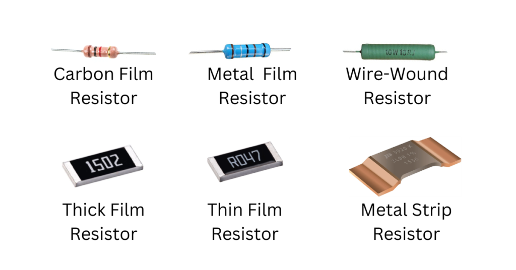
5.1.1 Carbon Film Resistors:
Construction: A carbon film is deposited on a ceramic substrate, with helical cuts to adjust resistance.
Pros: Low cost, moderate noise, and decent stability.
Cons: Higher tolerance (±5% typical), limited precision.
Identification: Color-coded bands (e.g., Red-Red-Brown-Gold = 220Ω ±5%).
Applications: General-purpose circuits (e.g., LED current limiting, pull-up/down resistors).
5.1.2 Metal Film Resistors:
Construction: A thin metal film (nickel-chromium) on a ceramic core, laser-trimmed for precision.
Pros: Tight tolerance (±1% or better), low noise, stable over temperature.
Cons: Slightly costlier than carbon film.
Identification: Color bands (precision) or printed labels.
Applications: Precision analog circuits, amplifiers, medical devices.
5.1.3 Wire-Wound Resistors:
Construction: A resistive wire (nichrome) wound around an insulating core, often coated in ceramic or enamel.
Pros: High power handling (up to 1000W), excellent stability.
Cons: Inductive at high frequencies, bulky.
Identification: Printed labels (e.g., “10Ω 50W”)—rarely color-coded.
Applications: Power supplies, motor controllers, braking systems.
5.1.4 Thick Film Resistors:
Construction: A paste of glass and metal oxides is screen-printed onto a ceramic substrate and fired at high temperatures.
Pros: Cost-effective, compact, and good for high-volume production.
Cons: Moderate tolerance (±5% typical, but can be ±1%), higher noise than metal film resistors.
Identification: Printed codes (SMD, e.g., “473”) or color bands (through-hole).
Applications: Consumer electronics (TVs, smartphones), automotive modules (e.g., ECUs, sensors).
5.1.5 Thin Film Resistors:
Construction: A thin metal alloy layer (e.g., tantalum nitride) is vacuum-deposited onto a ceramic or glass substrate.
Pros: Ultra-high precision (±0.1% or better), low temperature coefficient of resistance (TCR), excellent frequency response.
Cons: Expensive, sensitive to mechanical stress.
Identification: Printed labels (SMD, e.g., “1002” = 10kΩ ±0.1%) or color bands (through-hole).
Applications: Aerospace instrumentation, high-frequency RF circuits, precision electronic equipment.
5.1.6 Metal Strip Resistors:
Construction: Flat metal strips (often steel or aluminum) with a resistive alloy applied, typically in a pattern or meandering design to adjust resistance.
Pros: High surge tolerance, robust mechanical design, and excellent power handling capabilities.
Cons: Limited resistance range, typically higher values, and bulky compared to other resistor types.
Identification: Engraved or stamped values (e.g., “0.1Ω 20W”).
Applications: Current sensing in power supplies, industrial inverters, and other high power applications.
5.2 Variable Resistors
Variable resistors allow users to adjust resistance values manually or automatically, making them ideal for applications requiring fine-tuning or dynamic control. Below, we break down the most common types of variable resistors:
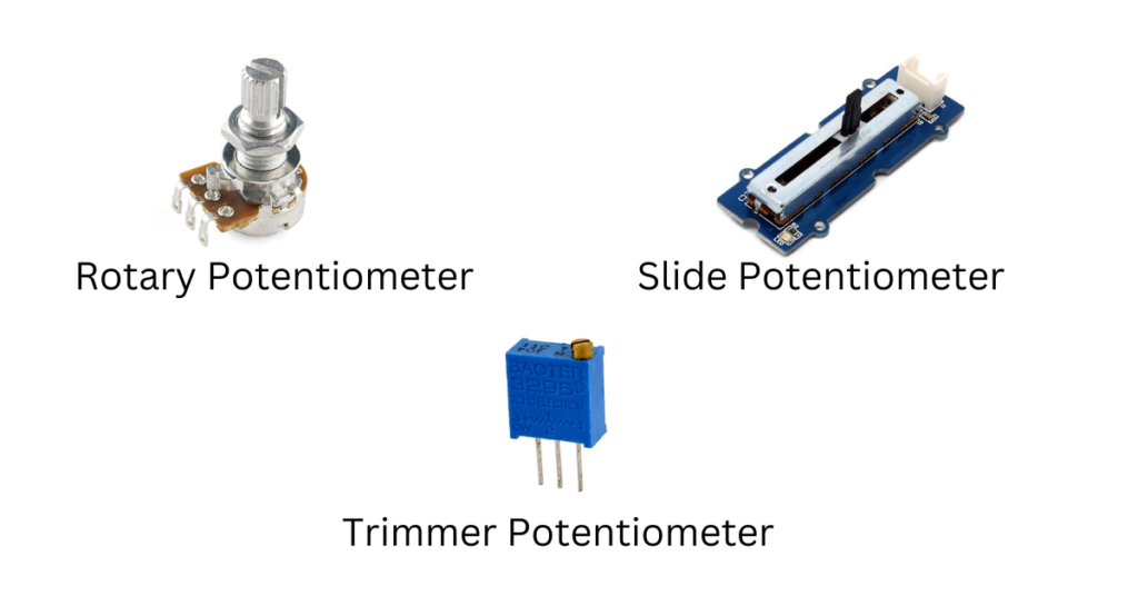
5.2.1 Potentiometers
Construction: A resistive track (carbon, cermet, or conductive plastic) with a sliding contact (wiper). Available in three main types:
- Rotary: Adjusted by rotating a knob (e.g., volume controls).
- Slide: Adjusted by sliding a lever (e.g., audio mixers).
- Trimmer: Small, screwdriver-adjusted potentiometers for calibration.
Pros: Easy to use, versatile, available in rotary and slide configurations.
Cons: Mechanical wear over time, limited precision in low-cost models.
Applications: Volume controls, dimmer switches, sensor calibration.
5.2.2 Digital Potentiometers
Construction: Integrated circuit (IC) with resistive elements and digital control interfaces (e.g., I2C, SPI).
Pros: Precise, programmable, compact, remote-controllable.
Cons: Higher cost, limited power handling compared to mechanical pots.
Applications: Automated calibration, audio equipment, programmable power supplies.
5.2.3 Rheostats:
Construction: A wire-wound resistive element with a sliding contact.
Pros: High power handling, simple design.
Cons: Bulky, less efficient compared to modern alternatives.
Applications: Motor speed control, lighting systems, power regulation.
5.3 Specialty Resistors
Specialty resistors are designed for specific applications, offering unique properties that go beyond standard resistance values. Below, we explore three key types: thermistors, photoresistors, and varistors.
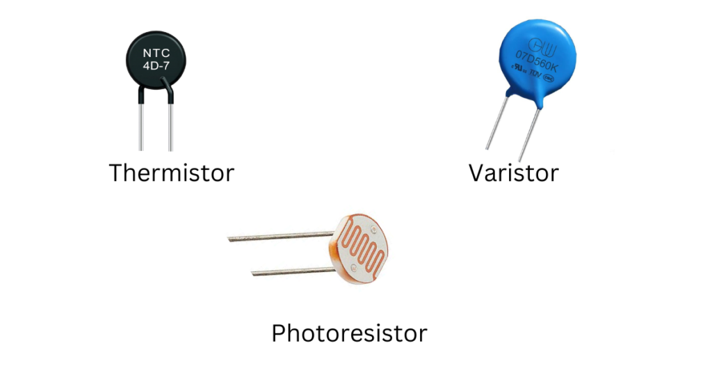
5.3.1 Thermistors:
Construction: Made from ceramic or polymer materials with temperature-sensitive resistance properties. Available in two types:
- NTC (Negative Temperature Coefficient): Resistance decreases as temperature rises.
- PTC (Positive Temperature Coefficient): Resistance increases as temperature rises.
Pros: High sensitivity to temperature changes, compact, cost-effective.
Cons: Non-linear response, limited temperature range compared to more advanced sensors.
Applications: Thermostats, HVAC systems, battery management, and circuit protection.
5.3.2 Photoresistors:
Construction: A semiconductor material (e.g., cadmium sulfide) whose resistance changes with light intensity.
Pros: Simple, inexpensive, responsive to visible light.
Cons: Slow response time, sensitivity degradation over time.
Applications: Automatic streetlights, camera exposure control, light-sensitive alarms.
5.3.3 Varistors :
Construction: Composed of zinc oxide particles sandwiched between metal plates, forming a voltage-dependent resistive network.
Pros: Excellent surge protection, fast response to voltage spikes.
Cons: Degrades after repeated surges, limited lifespan under high stress.
Applications: Surge protection in power strips, industrial equipment, and consumer electronics.
6. Packaging of Resistors
Resistors come in various packaging styles, each suited to specific applications and manufacturing processes. Below, we explore the most common resistor packages and their use cases.
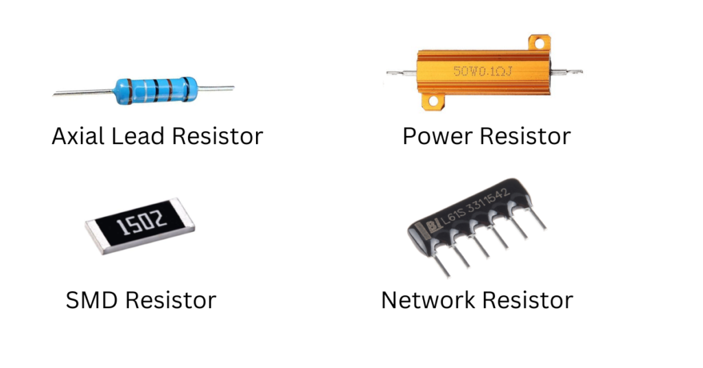
6.1 Through-Hole Resistors
Description: Resistors with axial or radial leads for insertion into printed circuit boards (PCBs).
Pros: Easy to handle, robust, ideal for prototyping and high-power applications.
Cons: Bulky, not suitable for compact designs.
Applications: DIY projects, industrial equipment, power supplies.
6.2 Surface Mount Resistors
Description: Compact resistors designed for surface mounting on PCBs. Common sizes include 0402, 0603, 0805, and 1206.
Pros: Small, lightweight, suitable for automated assembly.
Cons: Difficult to handle manually, limited power dissipation.
Applications: Consumer electronics (smartphones, laptops), IoT devices, compact circuits.
6.3 Power Resistors
Description: Designed to handle high power dissipation, often in metal or ceramic packages.
Pros: High power ratings, robust construction.
Cons: Large size, higher cost.
Applications: Motor drives, power supplies, industrial equipment.
6.4 Network Resistors
Description: Multiple resistors integrated into a single package (e.g., resistor arrays).
Pros: Saves space, improves consistency in matched resistors.
Cons: Limited flexibility in resistance values.
Applications: Signal conditioning, pull-up/pull-down networks.
7. Selection Criteria for Resistors
When selecting a resistor for a particular application, several factors must be considered . Here’s a focused guide to help you choose the right resistor:
7.1 Resistance value (Ω)
What to Consider: Ensure the resistance matches the circuit requirements (use Ohm’s Law for calculations).
Pro Tip: Stick to standard E-series values (e.g., E12, E24) for availability and cost-effectiveness.
7.2 Power Rating (W)
What to Consider: Choose a resistor with a power rating higher than the maximum power expected in the circuit.
Pro Tip: Derate the resistor (e.g., use 2x the calculated power) to ensure reliability and longevity.
7.3 Tolerance (%)
What to Consider: Precision circuits (e.g., amplifiers, sensors) require tight tolerance (±0.1% to ±1%), while general-purpose circuits can use ±5% or ±10%.
Pro Tip: Metal film and thin film resistors offer the best precision.
7.4 Temperature Coefficient (ppm/°C)
What to Consider: For circuits operating in varying temperatures, choose resistors with a low TCR (e.g., ±25 ppm/°C or better).
Pro Tip: Thin film resistors are ideal for temperature-sensitive applications.
7.5 Packaging
What to Consider:
- Through-Hole: Easy to handle, ideal for prototyping.
- Surface-Mount (SMD): Compact, suitable for high-density designs.
- High-Power Types: Wire-wound or metal strip resistors for power applications.
Pro Tip: Match the resistor package (e.g., 0402, 0603) to your PCB design.
7.6 Voltage Rating (V)
What to Consider: Ensure the resistor can handle the maximum voltage in the circuit without breaking down.
Pro Tip: Check the datasheet for voltage derating at high temperatures.
7.7 Material Type
What to Consider:
- Metal Film: Precision and low noise.
- Wire-Wound: High power handling.
- Carbon Film: Cost-effective for general use.
Pro Tip: Match the material to the application’s requirements (e.g., metal film for audio circuits).
7.8 Noise Characteristics
What to Consider: For sensitive circuits (e.g., audio, RF), choose resistors with low noise (e.g., metal film).
Pro Tip: Avoid carbon composition resistors in low-noise applications.
7.9 Environmental Considerations
What to Consider: Choose resistors rated for harsh conditions (e.g., high humidity, extreme temperatures) if needed.
Pro Tip: Look for automotive (AEC-Q200) or military-grade resistors for rugged applications.
7.10 Cost and Availability
What to Consider: Balance performance with budget constraints. Standard resistors are cost-effective for high-volume production.
Pro Tip: Use distributors with real-time stock availability to avoid delays.
8. Applications of Resistors
Resistors are fundamental components in virtually every electronic circuit, performing a wide variety of tasks. Below are some key applications:
Current Limiting: Protect LEDs and other components from excessive current.
Motor Control: Wire-wound resistors in motor drives and braking systems.
Power Supplies: Current sensing and voltage regulation.
Temperature Sensing: NTC/PTC thermistors in HVAC systems.
Patient Monitoring: Precision resistors in ECG and blood pressure monitors.
9. Conclusion
Resistors are fundamental components in electronic circuits, serving a variety of crucial functions such as controlling current, dividing voltage, and protecting other components. Understanding their types, characteristics, and proper selection criteria is essential for designing reliable and efficient electronic systems. By applying the knowledge gained from this article, you’ll be well-equipped to make informed decisions and ensure the optimal performance of your circuits.
To learn more about electronics and embedded systems, visit Maitronics for detailed guides, tutorials, and resources.
For any inquiries or feedback, feel free to reach out to us at [email protected].
Follow us on social media for updates, tutorials, and insights!
1 thought on “Resistor Types and Characteristics: A Complete Guide to Selection and Applications”
Comments are closed.